
Four local copper devices and one fiber run is a common edge-network problem: a small cabinet, a security post, a production cell, or a building-floor handoff needs to keep its RJ45 equipment while reaching a distant network over fiber. A 4 x 10/100/1000M TX and 1 x 1GE fiber/SFP device addresses that job without forcing a larger access switch into a space that does not need one.
The useful question is not simply “does it have an SFP?” It is whether the uplink medium, connector style, fiber type, link distance, and installed spare-stock policy match the site. Get one of those wrong and a modest copper-to-fiber extension becomes an avoidable truck roll.
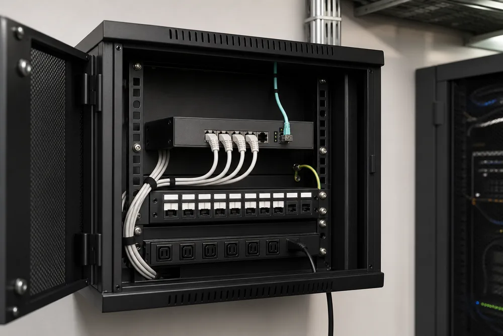
Key Takeaways: 4 x 10/100/1000M TX and 1 x 1GE Fiber/SFP for Simple Copper-to-Fiber Extension
- Four 10/100/1000Base-TX ports connect local copper endpoints at their negotiated Ethernet speed.
- A single 1GE fixed-fiber or SFP uplink carries the aggregation link onto optical cable.
- Fixed optics simplify a known, repeatable link; an SFP slot preserves flexibility for changing fiber requirements.
- Check the actual fiber plant, connector termination, operating environment, and power arrangement before ordering.
This port layout is built for consolidation, not for creating extra bandwidth upstream. Four copper ports may feed traffic toward one 1GE optical uplink, so the uplink is shared. That is usually sensible for ordinary edge equipment, but it deserves an honest traffic review where several cameras, storage devices, or high-rate industrial endpoints can transmit at once.
OPTONE describes its OPT-205 category as four 10/100/1000Base-TX RJ45 ports with one 1000Base-FX or SFP interface. That makes it a practical format for replacing a copper-only edge segment with a fiber-reachable one. See the available 4-port Gigabit RJ45 and 1GE SFP configurations before treating every version as interchangeable.
Configuration and Interface Comparison: Fixed-Fiber vs SFP Uplink Options
A fixed-fiber version is the cleaner choice where the network design is settled. You select the intended fiber mode and connector arrangement at procurement, install the matching patch lead, and reduce the chance that somebody later fits the wrong optical module. This is often attractive for standardized branch rollouts and repeat installations where the fiber route is known.
An SFP uplink changes the conversation. The switch supplies the slot; the optical interface is determined by the SFP selected for the link. That can be useful if sites differ in their installed fiber or if stocking one hardware platform matters more than locking every optic at the factory. It also adds a responsibility: the module must match the remote optic and the actual cable plant. An SFP that fits mechanically is not proof that the link will work.
WDM single-fiber configuration is an optical arrangement that sends and receives Ethernet traffic over one fiber strand by placing the two directions on separate wavelengths. It can preserve a scarce fiber core, but it requires the correct complementary optics at opposite ends. A WDM unit cannot be casually paired with an ordinary dual-fiber optic, and reversing the intended A/B pairing is a familiar commissioning error.
| Uplink approach | Best fit | What to verify |
|---|---|---|
| Fixed 1000Base-FX fiber port | Defined, repeatable fiber links | Fiber type, connector style, optical configuration, remote-end compatibility |
| 1GE SFP uplink | Projects needing optical-module flexibility | SFP compatibility, fiber plant, connector type, matching optic at the far end |
| WDM single-fiber option | Routes with only one available fiber core | Complementary wavelength pairing and correct installation at both ends |
How to Select the Right Unmanaged RJ45-to-Fiber Switch for Your Existing Link
Start at the far end, not with the switch front panel. Identify what terminates the optical link now: another switch, a media converter, an aggregation device, or a patch panel feeding an optic. Then inspect the fiber records. “Fiber installed” is not enough. You need to know whether the path uses single-mode or multimode fiber, whether one or two strands are available, and which connector interface is present at the equipment side.
For a deployment that requires unmanaged operation, confirm the operational behavior you expect rather than assuming it from the enclosure. Local teams usually care about basic link visibility, power input, mounting, environmental suitability, and whether any special configuration is required. These details matter more than a long feature list in a small edge cabinet.
- Document the copper endpoints. Count the RJ45 devices, their required link speeds, and their traffic patterns.
- Trace the optical path. Record fiber type, available strands, connector presentation, and remote-end equipment.
- Choose the uplink style. Use fixed fiber for a settled design, or an SFP option where module selection is part of the project plan.
- Check physical deployment conditions. Confirm power, cabinet space, mounting, temperature exposure, and service access.
- Validate before rollout. Test the selected switch and optical pairing against the intended remote device and patching arrangement.
Buyers often overlook connector conversion. A fixed-port variant may be available with SC, ST, or FC arrangements, while SFP modules commonly introduce their own connector expectations. Do not solve a link mismatch with a random chain of adaptors. Each added interface creates another contamination, loss, and labeling point. Review the OPT-205 fiber and SFP uplink options against the as-built record.
Frequently Asked Questions About 4-Port Gigabit Switches with SFP Uplinks
Small copper-to-fiber devices are often described loosely in quotations and project notes. That creates confusion because a product can perform media conversion while also providing several switched copper ports. The port count and traffic behavior are the useful clues.
Is this product a network switch or a fiber media converter?
It is best understood as a compact fiber Ethernet switch format with media-conversion duties. The four RJ45 ports connect local 10/100/1000Base-TX equipment, while the 1GE fiber or SFP interface extends the connection over fiber. A basic two-port media converter normally bridges one copper port to one fiber port. A four-copper-port design adds local Ethernet aggregation, which is why it suits a cluster of edge devices rather than a single endpoint.
Should I choose a fixed fiber port or an SFP uplink?
Choose a fixed fiber port if the cable type, connector format, and remote optical arrangement are already known and unlikely to change. It keeps selection simple and can make a repeat deployment easier to standardize. Choose an SFP uplink if you need to select optics per site, maintain flexibility for future replacement, or work across different optical requirements. In either case, confirm the remote device and both sides of the fiber link; the switch cannot correct an incompatible optic pair or contaminated connector.
OPTONE OPT-205 Category: Configurable 1G Fiber Ethernet Connectivity for Project and OEM Supply
OPTONE Technology Limited has supplied optical transceivers and fiber Ethernet products since 2003. Its OPT-205 category covers the relevant port architecture: four Gigabit-capable RJ45 ports and one 1G fiber interface, offered as fixed 1000Base-FX or SFP depending on configuration. Fixed fiber choices cited by OPTONE include single-mode, multimode, and WDM single-fiber forms, with SC, ST, or FC connector options.
That range is useful for project buyers because the correct unit can be aligned to the existing plant instead of forcing a generic bill of materials onto every site. For OEM procurement, configuration control is the real issue: define the requested interface arrangement, optical type, labeling requirements, documentation needs, and acceptance process before the purchase order is released. If an SFP version is selected, specify the module policy too—supplied module, approved compatible module, or customer-provided optic.
OPTONE also works across fiber media converters, fiber Ethernet switches, and optical interconnect products. For a compact edge extension, the relevant product page is the OPT-205 4 x 10/100/1000M TX and 1GE SFP series. Send the fiber and remote-equipment details with your inquiry; it is the fastest route to a configuration that can actually be installed.
Request Configuration Guidance, Documentation, Lead-Time and Pricing from OPTONE: https://fibertransceiver.com/contact/
Bring a short site record to the discussion: the number of copper devices, the remote-end equipment, fiber mode, strand availability, connector format, and any requirement for fixed optics, an SFP slot, or single-fiber WDM. Include deployment conditions and the quantity split by configuration if the project covers several locations. That gives OPTONE enough information to separate a suitable interface choice from a look-alike part number.
Ask for the applicable documentation, confirmation of the requested configuration, current lead-time, and pricing for the actual order quantity. If you are replacing installed equipment, photographs of labels and fiber terminations can prevent an expensive assumption. Use the product page for the category reference, then contact the supplier with the facts from the site.
Confirm Your 1GE Copper-to-Fiber Configuration
Review the OPT-205 category and prepare your fiber type, connector, remote-end optic, and deployment requirements before requesting project guidance or a quotation.
Need help selecting the right product?
Share your switch platform, link distance and quantity with an OPTONE engineer.
Talk to an Engineer →