
Why Optical Transceivers Are Chosen for Scalable Network Links
Network equipment changes more slowly than link requirements. A pluggable optical interface gives you a practical way to extend, alter, or repair a connection while retaining the switch, router, or server adapter already in service. That matters in data centers, enterprise campuses, ISP networks, and telecom environments where a port failure or a badly planned upgrade can affect more than one cabinet.
Fiber is also suited to links that exceed the practical distance or electromagnetic tolerance of ordinary copper patching. The module converts the host’s electrical signal into light for transmission through fiber, then converts received light back into an electrical signal at the far end. The result is a physical layer designed around the route and bandwidth requirement rather than a permanently attached cable assembly.
The commercial benefit is choice. A network team can keep spare modules for known port types, replace a failed optic without disturbing the permanent cable, and use different optical designs across the same estate where the host interfaces allow it. The trade-off is that every added choice creates another compatibility item to control. Labeling, approved part records, and pre-deployment checks are not bureaucracy; they prevent costly site visits.
How an Optical Transceiver Connects Electrical Ports to Fiber Infrastructure
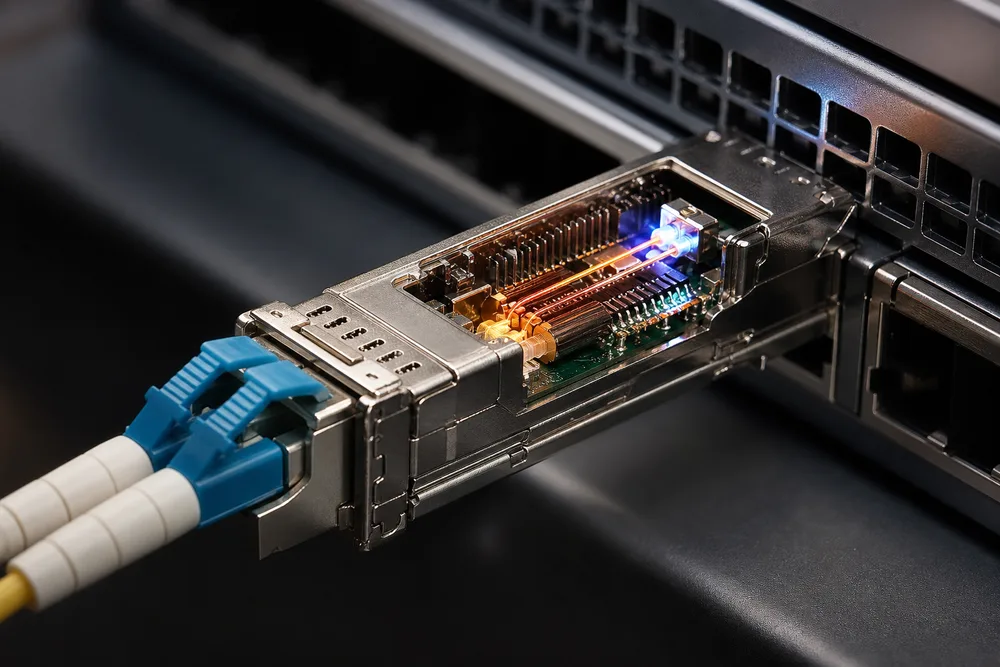
Inside an optical transceiver, the transmit side accepts the electrical lane or lanes presented by the host port and drives an optical source. The receive side detects incoming light and returns an electrical signal to the host. Control circuitry stores identification and operating information that the platform may read through the module interface.
That simple description hides the decisions that affect a real link. Optical power must be appropriate for the planned path. The fiber’s core type and condition influence what signal can reach the far end. Two ends of a duplex link must use compatible transmit and receive paths. In wavelength-based designs, each end must use the corresponding wavelength arrangement. A clean connector still cannot rescue mismatched optics.
Modern modules are specified as a system component, not as a generic light source. The useful specification set includes the host form factor, intended Ethernet or transport application, fiber type, connector interface, reach class, wavelength arrangement, operating temperature range, and vendor coding expectations. Leave one of those as an assumption and the risk moves to installation day.
When Optical Transceivers Are a Better Choice Than Copper, DAC, or AOC Links
Copper SFP products, direct-attach copper (DAC) assemblies, active optical cables (AOCs), and pluggable fiber optics all have a place. The best option depends on the route, service model, and how likely the link is to change.
DACs are often sensible for short, fixed interconnects inside or between adjacent racks. Their cable ends are integrated with the assembly, which can reduce component selection work. The downside appears when the planned route changes, a cable is damaged, or port migration requires a different length or interface. A DAC is a whole assembly replacement.
AOCs provide a pre-terminated active optical assembly and can be useful where a lightweight optical cable is preferred for a defined short route. They are less flexible than separate modules and fiber because the electronics and cable are one item. You cannot generally retain the cable and swap only the optics.
Copper SFP connections can work well for appropriate Ethernet-over-copper requirements, especially where existing copper infrastructure is intentional. They are not a substitute for fiber where distance, pathway conditions, or the installed network design calls for optical media.
Fiber reach and infrastructure reuse
Separate optical modules are usually the better fit when you already have permanent fiber between rooms, floors, buildings, or network zones. You can match the optic to the installed single-mode or multimode fiber rather than pulling a new integrated cable. This is where buyers avoid a common mistake: ordering an optic for the desired distance before confirming what fiber is actually in the tray.
Reuse is not automatic. Verify the fiber type, connector condition, polarity, splices, patch panels, and the actual route. Older multimode runs, mixed patching, contaminated end faces, and undocumented changes can make a nominally compatible selection unreliable.
Pluggability, upgrades, and replacement flexibility
Pluggability is valuable where operational continuity matters. A failed module can be replaced without replacing the host device or permanent fiber. During an upgrade, ports and optics can be planned together by interface family rather than treating every cable as a fixed asset.
It does not mean every port can accept every speed. A higher-capacity module may share a physical family with another module while requiring a different host electrical interface, software support, or breakout design. Confirm the platform documentation before assuming an upgrade is a simple swap.
Choose the Form Factor That Matches the Host Port and Network Capacity
Form factor is the first filter because it determines the module’s physical envelope and host-side interface family. Start with the exact port label and equipment documentation. Then identify the interface application supported on that port. The module’s printed speed is useful, but it is not enough on its own.
SFP, SFP+, SFP28, QSFP28, QSFP56, QSFP-DD, and OSFP families
OPTONE’s optical transceiver range includes SFP, SFP+, XFP, SFP28, QSFP+, QSFP28, QSFP56, QSFP-DD, and OSFP form factors across 1G to 800G product coverage. These families exist because network ports use different mechanical formats and lane arrangements as capacity increases.
SFP-family modules are compact, single-port pluggables used across several generations of network interfaces. QSFP-family modules use a larger format associated with multi-lane applications, while QSFP-DD and OSFP support higher-density interface designs. That is useful context, not a compatibility promise. Each host platform determines what it supports in a given cage and software release.
Why matching data rate alone does not confirm compatibility
Two modules can both be described around the same network capacity and still be unsuitable partners. The host may require a different form factor. The port may only support a defined set of electrical lanes. One optic may be intended for duplex fiber while another expects parallel fibers or wavelength multiplexing. A transport platform may also impose application-specific requirements that an Ethernet switch does not.
Ask for the full host make and model, port type, operating system or firmware context where relevant, and the intended link application. If breakout is planned, identify the supported breakout topology at both ends. Do not use a module’s shell shape as proof that it will operate.
Match the Transceiver to Fiber Type, Connector, Reach, and Link Design
A correct host-side choice is only half of the job. The optical side must match the physical infrastructure from end to end. Review the installed fiber records, inspect the patching arrangement, and identify what is already deployed at the remote end before finalizing a part number.
Single-mode and multimode fiber selection
Single-mode and multimode fiber are different transmission media, and the optic must be designed for the fiber in use. Single-mode fiber is commonly selected for longer routes and many campus, metro, telecom, and data-center interconnect applications. Multimode fiber is widely used for suitable shorter-reach links within buildings and data halls.
Do not select based on color conventions, a verbal description from an installer, or the length shown on a floor plan. Confirm the cable type from records or physical identification, then choose the applicable transceiver family and reach class. The usable link depends on the whole channel, including connectors, patch cords, panels, and any loss introduced by repairs or splices.
Duplex optics, BiDi links, and CWDM or DWDM applications
Duplex optics use separate transmit and receive fiber paths. They are straightforward where a paired fiber path is available and correctly polarized. BiDi optics send and receive on different wavelengths over a single fiber, making them useful when only one usable strand is available or when conserving installed fiber is more valuable than maintaining a duplex layout.
BiDi links require matched endpoints. The wavelength pairing must be complementary, so two identical-looking modules are not necessarily a valid pair. Mark each end clearly; field teams often lose time troubleshooting a link that has simply been fitted with the wrong BiDi counterpart.
CWDM and DWDM designs carry multiple wavelength channels over fiber infrastructure. They can support capacity growth where fiber availability is constrained, but channel planning becomes essential. Confirm the wavelength plan, passive components in the path, endpoint pairing, and the transport equipment’s requirements. These are not products to substitute casually based on connector type alone.
MSA Compliance and OEM Coding: What a Real Compatibility Check Requires
MSA compliance is valuable because multi-source agreements define common mechanical, electrical, and management-interface expectations for many pluggable optical module families. It supports interoperability at the module-interface level. It does not mean that every network platform will accept every MSA-compliant module without qualification.
OEM compatibility concerns how a switch, router, NIC, or transport platform identifies and accepts a module. Some equipment checks vendor information or requires coding aligned with its approved module policy. Others are more permissive. A module can be physically correct, electrically appropriate, and still be rejected or flagged by the host.
Validate the switch, router, NIC, or transport platform
A real optical transceiver compatibility check should include:
- the host manufacturer and exact device model;
- the port type, intended interface application, and supported module list where available;
- the software or firmware version if the platform’s support varies by release;
- the required form factor, fiber design, reach, and remote-end module arrangement;
- any OEM coding or vendor-lock policy used by the platform.
OPTONE describes its modules as MSA compliant and offers OEM compatibility options. Provide the platform details before ordering rather than asking for a generic “compatible optic.” That gives the supplier enough information to identify the intended coding and avoid a preventable return. You can review the available optical transceiver options from OPTONE once those host and link details are defined.
Use DDM and DOM Diagnostics to Monitor Link Health and Simplify Troubleshooting
DDM, often called DOM, lets supported optical modules report operating data to a compatible host. Readings commonly include module temperature, supply voltage, laser bias current, transmitted optical power, and received optical power. These values give a network team evidence before it dispatches someone to a rack or remote cabinet.
A declining received-power reading can point toward connector contamination, a damaged patch lead, unexpected attenuation, or an issue at the far end. An abnormal temperature or bias-current trend may justify closer inspection of a module or its operating conditions. Diagnostics are especially useful when comparing a known-good link with a problem link that uses the same design.
DOM is not a guarantee of root cause. Its accuracy and alarm behavior depend on the module and host interpretation, and not every fault appears as a neat threshold alarm. Bad polarity, an unsupported module, a wrong wavelength pair, and a disabled switch port can all leave you with no useful optical story. Use diagnostic data alongside interface counters, event logs, fiber inspection, and configuration checks.
OPTONE lists DDM/DOM support in its optical transceiver range. Confirm both the module’s diagnostic support and the host’s ability to display and act on that data before making monitoring a procurement requirement.
What to Verify Before Purchasing Optical Transceivers from OPTONE
OPTONE manufactures optical transceiver modules in Shenzhen, China, along with fiber media converters, AOC/DAC cables, and fiber Ethernet switches. Its stated transceiver coverage spans 1G to 800G and includes standard pluggable families, BiDi, CWDM, DWDM, and copper SFP products. That breadth can simplify sourcing, but the order still needs a clear technical definition.
For a production order, ask the supplier to confirm the proposed part against your platform and link details. If your environment has temperature constraints, specify whether commercial or industrial operating temperature options are required rather than treating the enclosure location as an afterthought. A module installed near process equipment, outdoors, or in a poorly controlled cabinet may need a different operating range than one in a conditioned data hall.
OPTONE states that it performs burn-in testing, a process in which modules are operated before shipment to help identify early-life faults that may appear under use. Its site also references TX/RX power verification. These process checks are relevant quality controls, yet they do not replace acceptance testing in your own host equipment and fiber channel. The platform, cable path, and final configuration remain part of the deployed system.
For unfamiliar equipment or a high-consequence rollout, request samples and test them in the actual host model before committing volume. Check link establishment, error counters, DOM visibility where required, remote-end interoperability, and behavior after a reboot or port reset. For sourcing discussions, use OPTONE’s OEM-compatible optical transceiver enquiry route with the host and fiber information already assembled.
Optical Transceiver Selection Checklist for Quotes, Samples, and Volume Orders
- Host: Record the exact switch, router, NIC, or transport platform model, port type, and relevant software context.
- Interface: Confirm the required form factor and network application; do not select on capacity label alone.
- Fiber path: Identify single-mode or multimode fiber, connector arrangement, polarity, route condition, and required reach.
- Endpoint design: Specify duplex, BiDi, CWDM, DWDM, breakout, or other link architecture, including the required remote-end counterpart.
- Compatibility: Check MSA interface expectations and any OEM coding requirement for the host platform.
- Monitoring: Decide whether DDM/DOM visibility is needed and verify that the host reads the diagnostics you expect.
- Environment: State commercial or industrial operating temperature needs before the quote is issued.
- Validation: For new combinations, test samples in the intended platform and fiber path before approving a volume order.
Send that completed set of details with your OPTONE optical transceiver quote request. It gives the supplier a defined link to match, and gives you a purchase decision based on compatibility rather than assumption.
Need help selecting the right product?
Share your switch platform, link distance and quantity with an OPTONE engineer.
Talk to an Engineer →