
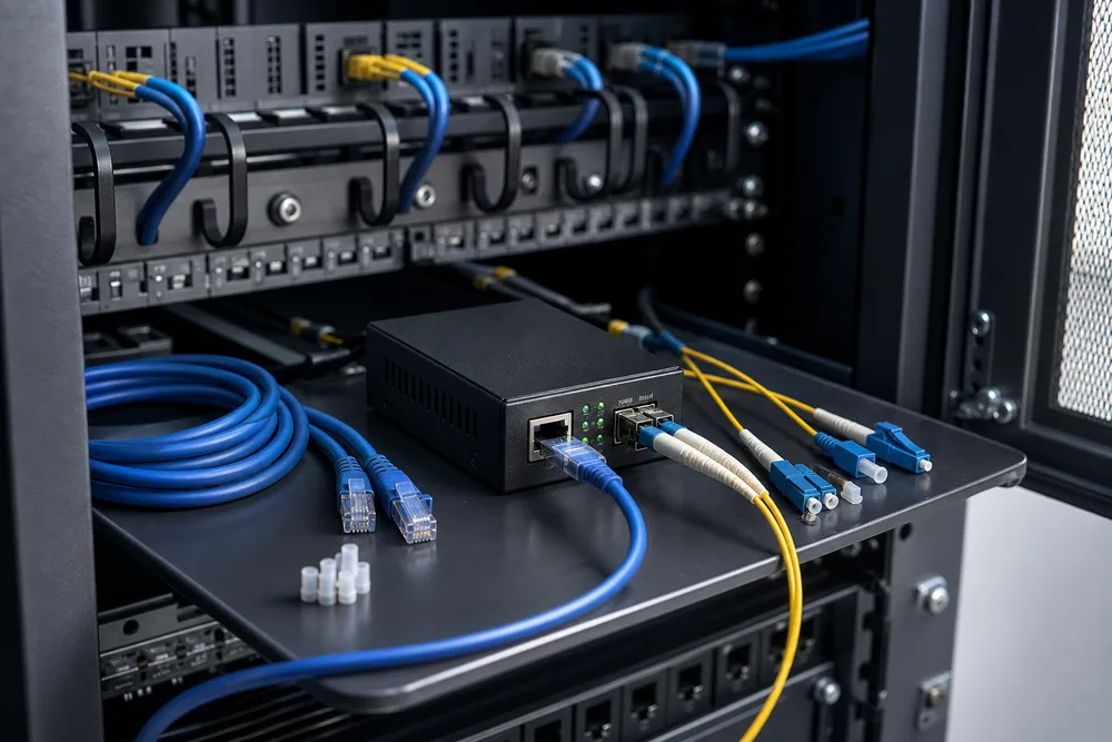
Key Takeaways: Match the Gigabit Copper Port, Fiber Interface and Remote-End Device Before Ordering
- Confirm that the copper endpoint supports the required 10/100/1000Base-T operating mode, not merely an RJ-45 connector.
- Specify fiber mode, connector or SFP arrangement, wavelength and WDM pairing as one matched link design.
- Check whether link-fault visibility is required at both ends before relying on LFP during fault isolation.
- Test jumbo-frame handling and auto-negotiation against the actual switch, camera, NVR or access device before rollout.
The costly mistake with Fiber Media Converters is ordering “Gigabit” at both ends and treating the fiber side as a detail. It is not. An OPTONE OPT-2200-series unit presents one 10/100/1000Base-T RJ-45 port and one 1000Base-FX or SFP fiber connection, so the copper device, optical path and far-end converter must be selected as a set. A single-mode WDM unit cannot form a link with an ordinary dual-fiber converter. Nor can an SFP-slot model solve an incompatible optic selection.
Start with the remote device. Record its port speed behaviour, the installed fiber plant, connector type, available fiber count and the required service outcome. That discipline prevents the familiar site visit where power is present, LEDs are lit, and the link still will not pass traffic.
Fiber Media Converter FAQ: Which Model, Fiber Type and Features Are Right for My Network?
Choose a fixed-fiber model when the installed cable, connector and link design are settled; choose an SFP model when optical flexibility is genuinely needed. For a standard copper-to-Gigabit-fiber extension, the OPT-2200 family is intended for 1 × 10/100/1000Base-T and 1 × 1000Base-FX/SFP connectivity. The correct fiber choice follows the cable plant: multi-mode and single-mode fibers are not interchangeable, and the supported reach depends on the selected model and fiber mode.
WDM is appropriate where only one usable fiber strand exists. It requires a complementary unit at the far end, with the intended wavelength pairing. Buyers often omit that last point from an RFQ, then receive two units that are electrically correct but optically unable to communicate. If your sites change often, review the OPT-2200 Gigabit media converter options with the required optic and remote-end device listed together.
OPT-2200, OPT-3200 WDM and OPT-2200A SFP: Comparison for a Gigabit Ethernet-to-Fiber Link
These names describe different purchasing routes, not a hierarchy of performance. Fixed-interface units suit repeatable deployments. WDM variants conserve fibers. The OPT-2200A uses an SFP slot, giving you a way to align the converter with the optical interface selected for a project. The selection should be driven by the link plan, not by a preference for the most configurable part.
| Option | Fiber-side approach | Best procurement use | Check before release |
|---|---|---|---|
| OPT-2200 fixed-fiber | Fixed SC, ST or FC option | Known cable and connector standard | Fiber mode and connector selection |
| OPT-3200 WDM | Single-fiber WDM variant | One-strand fiber routes | Complementary wavelength pairing |
| OPT-2200A | SFP slot | Projects needing optic selection flexibility | SFP type and full link compatibility |
Fixed-Fiber OPT-2200 Models: When SC, ST or FC Connector Options Fit the Project
Fixed-fiber OPT-2200 models fit projects where the installed connector convention is already known and unlikely to change. SC is common in many structured fiber installations, while ST or FC may be encountered in established telecom and industrial estates. Match the converter to the patching arrangement already in the cabinet; using adaptor chains to correct a poor ordering decision adds loss points and makes fault tracing harder.
Confirm multi-mode or single-mode operation before naming the connector. Connector geometry does not identify fiber mode. Also check the actual patch cords on site, especially in buildings with years of alterations and incomplete drawings.
OPT-3200 WDM and OPT-2200A SFP Models: Single-Fiber Topology Versus SFP Flexibility
OPT-3200 WDM is the practical choice where a link must run over one fiber, while OPT-2200A suits projects that need an SFP-defined fiber interface. WDM sends and receives over different wavelengths on the same strand. The far-end unit must use the complementary wavelength arrangement; identical WDM ends are not a valid pair.
An SFP slot offers flexibility, but it also moves responsibility to the specification. State the desired fiber mode, wavelength, connector and distance requirement for the optic, then verify it against the remote optic or converter. Do not treat “SFP” as a universal optical standard.
How to Specify and Commission a 1 × 10/100/1000Base-T to 1 × 1000Base-FX/SFP Media Converter
A clean purchase order separates the copper requirement from the optical requirement, then identifies the device at the other end. That is more useful to a supplier than a vague request for an Ethernet-to-fiber converter, and it gives your installation team a workable acceptance checklist.
Pre-Order Compatibility Checklist: Copper Interface, Fiber Mode, Wavelength, Distance and Pairing
Specify the complete link, including both ends, rather than describing one converter in isolation. Use this sequence before issuing an order:
- Identify the local copper device and confirm its required 10/100/1000Base-T operating behaviour.
- Record the installed fiber as single-mode or multi-mode, plus the available strand count and connector presentation.
- For WDM, identify the complementary wavelength pair required at the remote end.
- For OPT-2200A, state the SFP interface required rather than leaving optic selection open.
- Confirm the distance requirement against the selected model and fiber mode, then list the remote-end converter, switch or optic.
That record is also the right basis for a sample test. It catches mismatched patch leads and WDM pairs before equipment is distributed across sites.
Installation Checks: LFP, Auto-Negotiation, Auto MDI/MDI-X and 9K Jumbo-Frame Requirements
Link Fault Pass-Through (LFP) is the OPT-2200-series link-status mechanism that can reflect a fault on one segment toward the other interface. In practice, a fiber break can cause the copper-facing side to show a link condition that alerts the attached switch or endpoint, instead of leaving a misleading local copper link up. Its value is operational: technicians find the failed span faster. Verify the behaviour with the actual far-end equipment, because link indication and fault response are a property of the full connection, not one box alone.
Auto-negotiation and Auto MDI/MDI-X reduce copper-side setup errors, particularly with mixed patch-cord types. They do not repair a speed setting forced incorrectly on an attached switch. The family also lists 9K-byte jumbo-frame support; if storage, aggregation or another application sends large frames, test the entire path. One device with a smaller frame limit can produce an intermittent-looking problem that is really a policy mismatch.
OPTONE Gigabit Media Converter Positioning: Clear Boundaries Between 1000Base-FX, Fast Ethernet and 10G Families
The OPT-2200 series belongs in a Gigabit access or edge link where one copper device needs a 1000Base-FX or SFP fiber handoff. It is not a substitute for a Fast Ethernet converter if the project is deliberately built around lower-speed equipment, and it should not be specified as a 10G product because the fiber cable happens to be capable of higher rates. Port speed and interface family remain the boundary.
OPTONE’s wider range includes commercial, industrial, PoE, WDM and 10G Ethernet-to-fiber products. Those categories solve different problems. Temperature environment, power delivery, fiber conservation and throughput should be declared early, not patched into a Gigabit converter request after the BOM is approved.
Why LFP and Fiber-to-Copper Link Visibility Matter in Surveillance, Campus, Enterprise and Access Deployments
Link visibility matters because field teams need to distinguish a fiber fault from a powered-but-isolated endpoint. In surveillance deployments, a camera-side connection may appear normal locally while the upstream fiber span has failed. In campus, enterprise and access networks, the same ambiguity slows incident handling and can trigger needless replacement of switches or endpoint equipment.
LFP can make that fault state more visible across the media boundary, provided the complete design has been tested. It does not replace optical cleaning, correct patching, bend-radius discipline or a documented fiber route. For project teams comparing variants, the OPTONE 1000Base-FX and SFP converter listing is the appropriate reference point for available OPT-2200-series configurations.
Request a B2B Quote, Sample-Test Guidance or Product Consultation from OPTONE: https://fibertransceiver.com/products/fiber-media-converters/110-100-1000m-tx-and-11000m-fx-sfp-opt-2200-series/
Send OPTONE the copper endpoint type, fiber mode, connector arrangement, strand availability, required link distance and details of the remote device. For WDM, include the intended pair. For an SFP deployment, name the required optical interface. Those details let the sales and engineering team recommend a suitable configuration instead of returning a generic Gigabit quote.
If the project has mixed legacy fiber, unknown patch-panel records or a large surveillance rollout, ask for sample-test guidance before committing to the full quantity. Test the converter pair with your switch settings, real patch cords and actual traffic profile. Then release the production order with the approved model and pairing recorded on the purchase order.
Discuss your OPT-2200-series link requirement
Request a B2B quote, sample-test advice or configuration review with your copper port, fiber type and far-end equipment details.
Need help selecting the right product?
Share your switch platform, link distance and quantity with an OPTONE engineer.
Talk to an Engineer →